Update 18th April 2016: The helicopter HB-YNB has now 311 total hours (flying-, not blockhours!) This means about 100 hours during the last 12 month.
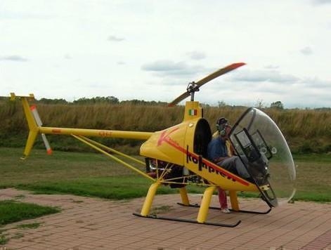
First contact with the Helicopter (CH-7 Heli-Sport)
What you see is the new model Charlie with new cowling and the gear fairings for better and faster cruise performance. Together with Ligi Barbero I could do a one hour test flight. Ligi is a very good flight instructor and he had no fear to let me try everything I wanted to find out, including a simulated auto-rotation. After this weekend I was completely convinced, that this is the helicopter I’m going to build Modell Charlie, see the carbon fairings and new shaped engine cowling
Preparation for 1st take-off
![FP03122006A00011[1]](https://kistleronline.ch/wp-content/uploads/2015/02/FP03122006A000111.jpg)
Is there room enough for my legs?
July 2006: I decided to pick up the kit in Torino myself, not only because the shipment and the cage would be very expensive, but also because I thought, that it would be a nice trip to Torino. We departed on a Sunday afternoon and arrived in a nice small hotel about 8pm. After a delicious Italian meal and a very nice wine we slept very well and were ready the next morning at the Strada Trafero del pino, 102-10132 Torino as agreed, 9am. After a very warm welcome by Claudio Barbero we started to pack Armin’s Ford-Transit. Our aim was to show up at customs at Ponte Tresa, a small border crossing-point near the city of Lugano, not later than 3pm. We were informed that the customs close their offices at 6pm. To be there rather early was a good decision. It turned out that the Italian custom officer was not happy with my papers. He wanted to be sure that we were not going to export critical military material. Thank God, Claudio Barbero was still in his office and could provide the custom office with the required declaration. The swiss customs-officer then was very kind, he even worked overtime to let us pass, a few days later I promptly received all the papers I will need later on when I will do the registration of the helicopter at FOCA. Late in the evening we arrived in Furna /Switzerland and quickly unpacked the Ford and stowed everything in the workshop.
![FP03122006A00015[1]](https://kistleronline.ch/wp-content/uploads/2015/02/FP03122006A000151.jpg) Welding the fuselage, Claudio Barbero, right, fuselage is under pressure to make sure there’s no leak
Welding the fuselage, Claudio Barbero, right, fuselage is under pressure to make sure there’s no leak
![FP03122006A00016[1]](https://kistleronline.ch/wp-content/uploads/2015/02/FP03122006A000161.jpg) Armin Egli, a good friend was so kind as to help me picking up the 1st Kit with his car.
Armin Egli, a good friend was so kind as to help me picking up the 1st Kit with his car.
![FP03122006A00017[1]](https://kistleronline.ch/wp-content/uploads/2015/02/FP03122006A000171.jpg) Happy but tired we arrived late at night in Furna
Happy but tired we arrived late at night in Furna
At home, I firstly had to find out what was / is in all the boxes! First kit, lot 1, includes basically all material without the main gearbox, tail rotor, rotor blades and engine. Everything is nicely packed and numbered, so the material is easy to find later on when assembling starts following the construction manual. The fuselage comes with a primer on it; one has just to select his favourite colour and can apply it. I decided to use the new bright and shiny orange Ford is using for their new car. From my previous project I knew a good paint shop in Pfaeffikon, Carrosserie Sandtner AG, Spenglerei + Spritzwerk, www.sandtner.ch. I prepared everything I thought should be painted and got it ready to be picked up. Horst Sandtner was so kind and lent me his mazda to carry all the stuff to bring it to his paint shop and back to my workshop.
![FP03122006A0001E[1]](https://kistleronline.ch/wp-content/uploads/2015/02/FP03122006A0001E1.jpg) …still an almost empty workshop…..
…still an almost empty workshop…..
![FP03122006A0001F[1]](https://kistleronline.ch/wp-content/uploads/2015/02/FP03122006A0001F1.jpg) Content checked and ready to be used!
Content checked and ready to be used!
![FP03122006A0001G[1]](https://kistleronline.ch/wp-content/uploads/2015/02/FP03122006A0001G1.jpg) First lot ready to paint.
First lot ready to paint.
First assembly steps(26.08.2006)
After finding out how the construction manual works, I could start with the first steps. (CD, HTML based, instead of the manual, the lap-top is required in the workshop.) I quickly found out, that the bolts used to mount the skids to the gear were too short, 1-3 threads were not visible after tightening the nut. I know that this will not be accepted during the EAS (http://www.experimental.ch/) / FOCA (http://www.aviation.admin.ch/) inspection later on. Consequently I had to order a „mechanic’s kit, bolts and nuts“ from Aircraft Spruce.
![FP03122006A0000K[1]](https://kistleronline.ch/wp-content/uploads/2015/02/FP03122006A0000K1.jpg) Back from Sandtner, a very nice job!
Back from Sandtner, a very nice job!
![FP03122006A0000L[1]](https://kistleronline.ch/wp-content/uploads/2015/02/FP03122006A0000L1.jpg) First step is to put the gear on to the skids
First step is to put the gear on to the skids
![FP03122006A0000M[1]](https://kistleronline.ch/wp-content/uploads/2015/02/FP03122006A0000M1.jpg) …and after a while it already looks like a helicopter!
…and after a while it already looks like a helicopter!
Pedals(09.09.2006)
The installation of the pedals and the corresponding rod until up to where the tail boom starts was a nice and easy job.
![FP29102006A00011[1]](https://kistleronline.ch/wp-content/uploads/2015/02/FP29102006A000111.jpg) Installation of Pedals
Installation of Pedals
![FP29102006A00012[1]](https://kistleronline.ch/wp-content/uploads/2015/02/FP29102006A000121.jpg) Tail Rotor: First direction change
Tail Rotor: First direction change
![FP29102006A00013[1]](https://kistleronline.ch/wp-content/uploads/2015/02/FP29102006A000131.jpg)
Tail Rotor: 2nd direction change
Assembly of Tailboom(10.09.2006)
The installation of the two bearing holder inside the tail boom was not easy. For me the instruction in the manual was not clear enough. In fact I had to remove the two holders again (!) after installation to interchange them. I made a short sketch, just in case I have to do it again next time. -:)
![FP03122006A0000H[1]](https://kistleronline.ch/wp-content/uploads/2015/02/FP03122006A0000H1.jpg) Front end
Front end
![FP03122006A0000I[1]](https://kistleronline.ch/wp-content/uploads/2015/02/FP03122006A0000I1.jpg) Rear end, ready to install tailrotor gearbox
Rear end, ready to install tailrotor gearbox
![FP03122006A0000J[1]](https://kistleronline.ch/wp-content/uploads/2015/02/FP03122006A0000J1.jpg) Waiting to be installed after engine installation
Waiting to be installed after engine installation
Installation of Collective and Cyclic (10.09.2006)
A very nice job to do! The quality of the parts is amazing. Each step is very well illustrated in the manual.
![FP29102006A0001A[1]](https://kistleronline.ch/wp-content/uploads/2015/02/FP29102006A0001A1.jpg) only the cyclic itself has do be connected
only the cyclic itself has do be connected
![FP29102006A0001B[1]](https://kistleronline.ch/wp-content/uploads/2015/02/FP29102006A0001B1.jpg) ready to connect to the engines cables
ready to connect to the engines cables
![FP29102006A00019[1]](https://kistleronline.ch/wp-content/uploads/2015/02/FP29102006A000191.jpg) Collective, Cyclic together, view from left rear
Collective, Cyclic together, view from left rear
Safety pin collective (21.10.2006)
These two bolts are turning with the collective.These nuts originally are metal self locking types. To be on the safe side I replaced them with castle nuts, drilled a hole and used a safety pin.
![FP18112006A00005[1]](https://kistleronline.ch/wp-content/uploads/2015/02/FP18112006A000051.jpg) Right
Right
![FP18112006A00006[1]](https://kistleronline.ch/wp-content/uploads/2015/02/FP18112006A000061.jpg) Left
Left
Rotax 912/914 line maintenance seminar (23.10.2006)
Being used to operate the Rotax 912 in my Kitfox I found it very useful to participate and spend one and a half day for these two engines, 912 and 914. (See: Franz-Aircraft) I got a lot of hints and tricks during the two days and I’m sure, it will make the installation / operation of the engine in my helicopter easier later on.
![FP03122006A0001H[1]](https://kistleronline.ch/wp-content/uploads/2015/02/FP03122006A0001H1.jpg) Do not turn this connector! (controls fuelpressure during high engine power)
Do not turn this connector! (controls fuelpressure during high engine power)
![FP03122006A0001I[1]](https://kistleronline.ch/wp-content/uploads/2015/02/FP03122006A0001I1.jpg) Turbine with waste gate
Turbine with waste gate
![FP03122006A0001J[1]](https://kistleronline.ch/wp-content/uploads/2015/02/FP03122006A0001J1.jpg) Oel-pump, a second layer is connected on Rotax 914 for return oil from turbine
Oel-pump, a second layer is connected on Rotax 914 for return oil from turbine
Preparing water/oil cooler (04.11.2006)
Preparation of the cooling system, waiting to be installed after engine installation
![FP12112006A0000S[1]](https://kistleronline.ch/wp-content/uploads/2015/02/FP12112006A0000S1.jpg) Watercooling (small Fan)
Watercooling (small Fan)
![FP12112006A0000T[1]](https://kistleronline.ch/wp-content/uploads/2015/02/FP12112006A0000T1.jpg) Oil & Watercooler (big Fan)
Oil & Watercooler (big Fan)
![FP12112006A0000U[1]](https://kistleronline.ch/wp-content/uploads/2015/02/FP12112006A0000U1.jpg) Both together, ready to install (this system will be replaced later on as a more efficient cooler-system is available)
Both together, ready to install (this system will be replaced later on as a more efficient cooler-system is available)
Stby instruments/collision avoiding system) (05.11.2006)
Since I intend to install the Dynon FlightDEK-D180 instrument, I will need a liquid compass as back-up, a stby ASI and a stby Altimeter. The EWC100 is available from Ediatec (http://www.ediatec.ch/), it contains an obstacle database and also warns you of conflicting traffic (if the other traffic is also equipped with Flarm or EWC100 and closer than 2km).The digital display starts at a distance of 2km and below.
![FP03122006A0001K[1]](https://kistleronline.ch/wp-content/uploads/2015/02/FP03122006A0001K1.jpg) ECW100
ECW100
![FP03122006A0001L[1]](https://kistleronline.ch/wp-content/uploads/2015/02/FP03122006A0001L1.jpg) EWC100, GPS Antenna, Data Antenna, Power Cable
EWC100, GPS Antenna, Data Antenna, Power Cable
![FP03122006A0001M[1]](https://kistleronline.ch/wp-content/uploads/2015/02/FP03122006A0001M1.jpg) Stby Instrument: ASI & Altimeter
Stby Instrument: ASI & Altimeter
Installation of battery holder (18.11.2006)
Installation of battery holder and connection of ground cable to the fuselage. 24th Nov 06: I received the callsign / numberplate from FOCA: HB-YNB (lateron battery installed more forward, below foot-area, CG issue)
![FP03122006A0001A[1]](https://kistleronline.ch/wp-content/uploads/2015/02/FP03122006A0001A1.jpg) Fuselage-side
Fuselage-side
![FP03122006A00018[1]](https://kistleronline.ch/wp-content/uploads/2015/02/FP03122006A000181.jpg) Battery Holder with Ground Connection
Battery Holder with Ground Connection
![FP03122006A00019[1]](https://kistleronline.ch/wp-content/uploads/2015/02/FP03122006A000191.jpg) Battery-side
Battery-side
Implementation/adaption of Dynon DEK180 (06.01.2007)
Instead of the Rotax Fly-Dat I will use the Dynon DEK 180. On first glance just „a minor change“ but a lot of work!
![FP12052007A0000N[1]](https://kistleronline.ch/wp-content/uploads/2015/02/FP12052007A0000N1.jpg) Working with the electric system
Working with the electric system
![FP12052007A0000O[1]](https://kistleronline.ch/wp-content/uploads/2015/02/FP12052007A0000O1.jpg) Dynon part of electric system
Dynon part of electric system
![FP12052007A0000P[1]](https://kistleronline.ch/wp-content/uploads/2015/02/FP12052007A0000P1.jpg) Engine cable with tags
Engine cable with tags
Cabin installation with my brother Guido (01.04.2007)
This is the first try to fix the cabin onto the Fuselage. But to take a seat for the very first time is a lot of fun! We both together decided to loose some weight until the very first flight!
![FP12052007A0000T[1]](https://kistleronline.ch/wp-content/uploads/2015/02/FP12052007A0000T1.jpg) First try
First try
![FP12052007A0000U[1]](https://kistleronline.ch/wp-content/uploads/2015/02/FP12052007A0000U1.jpg) Fixing cabin lower part
Fixing cabin lower part
![FP12052007A0000V[1]](https://kistleronline.ch/wp-content/uploads/2015/02/FP12052007A0000V1.jpg) We both together decided to loose some weight until the very first flight!
We both together decided to loose some weight until the very first flight!
Pick-up of 2nd kit, installation of mainrotor gearbox (01.04.2007)
We could pick up the 2nd part of the Kit March 26th 2007, everything worked fine and this time custom clearing was very quick. Content of Kit 2 was: Main Rotor Gear with Mast, Tail Rotor and the Blades.
![FP12052007A0000Q[1]](https://kistleronline.ch/wp-content/uploads/2015/02/FP12052007A0000Q1.jpg) My brother Guido, looking to be very precise
My brother Guido, looking to be very precise
![FP12052007A0000S[1]](https://kistleronline.ch/wp-content/uploads/2015/02/FP12052007A0000S1.jpg) According installation manual: Tilt after installation: 2.5° forward and .5° to the right
According installation manual: Tilt after installation: 2.5° forward and .5° to the right
![FP12052007A0000R[1]](https://kistleronline.ch/wp-content/uploads/2015/02/FP12052007A0000R1.jpg) Weight about 35-40kgs
Weight about 35-40kgs
Cabin (05.04.2007)
To adjust the cabin on the fuselage took a while, but all in all a perfect job they do at Heli Sport!
![FP12052007A0000W[1]](https://kistleronline.ch/wp-content/uploads/2015/02/FP12052007A0000W1.jpg) Cabin, lower part
Cabin, lower part
![FP12052007A0000X[1]](https://kistleronline.ch/wp-content/uploads/2015/02/FP12052007A0000X1.jpg) Gear Fairing
Gear Fairing
![FP12052007A0000Y[1]](https://kistleronline.ch/wp-content/uploads/2015/02/FP12052007A0000Y1.jpg) Cabin, ready to fix
Cabin, ready to fix
Adjustment of Canopy (21.04.2007, on my birthday!)
Fixing of canopy takes some time, a remaining gap will be covered later. Next step is covering the rear side of cabin with fireproof material.
![FP12052007A0000Z[1]](https://kistleronline.ch/wp-content/uploads/2015/02/FP12052007A0000Z1.jpg) Opening-closing hinge
Opening-closing hinge
![FP12052007A00010[1]](https://kistleronline.ch/wp-content/uploads/2015/02/FP12052007A000101.jpg) Canopy closed
Canopy closed
![FP12052007A00011[1]](https://kistleronline.ch/wp-content/uploads/2015/02/FP12052007A000111.jpg) First closing-opening from inside
First closing-opening from inside
Fire Wall (26.05.2007, on my birthday!)
Material: 0.3mm,steel, Glue: GYSO (www.gyso.ch) Polyflex 444, Paint: Dupli-Color, silver, heat-resistant to 800° C
![FP03062007A00003[1]](https://kistleronline.ch/wp-content/uploads/2015/02/FP03062007A000031.jpg) Fire-wall(Swiss Modification)
Fire-wall(Swiss Modification)
![FP03062007A00004[1]](https://kistleronline.ch/wp-content/uploads/2015/02/FP03062007A000041.jpg) Ready for paintshop
Ready for paintshop
![FP03062007A00002[1]](https://kistleronline.ch/wp-content/uploads/2015/02/FP03062007A000021.jpg) 0.3mm steel, ready to glue on
0.3mm steel, ready to glue on
Fixing/adjustment of cowling (02.06.2007)
Before painting all the adjustments have to be done, also the cutout for the fuel filler cap. The inside of the cowlig doors are painted with heat resistant paint, silver, 800°C
![FP03062007A00005[1]](https://kistleronline.ch/wp-content/uploads/2015/02/FP03062007A000051.jpg) Installation of tailboom, to have the center for the cowling
Installation of tailboom, to have the center for the cowling
![FP03062007A00006[1]](https://kistleronline.ch/wp-content/uploads/2015/02/FP03062007A000061.jpg)
![FP03062007A00007[1]](https://kistleronline.ch/wp-content/uploads/2015/02/FP03062007A000071.jpg) Rubber band installation
Rubber band installation
Painting (16.06.2007)
![FP04082007A0001W[1]](https://kistleronline.ch/wp-content/uploads/2015/02/FP04082007A0001W1.jpg)
![FP04082007A0001X[1]](https://kistleronline.ch/wp-content/uploads/2015/02/FP04082007A0001X1.jpg)
Rigging (04.08.2007)
Rigging of Cyclic Control and Collective.
Stick fully aft must bring a pitch up of 16°, stick full down must bring a pitch down of 14° on water level indication.
Stick full left must bring 9-10° bank, stick full right must bring 8-9° bank indication on water level.
Collective: Adjust to have a 2mm distance from the bottom in the slot. (Collective in full down position
![FP04082007A0001Y[1]](https://kistleronline.ch/wp-content/uploads/2015/02/FP04082007A0001Y1.jpg) Cyclic
Cyclic
![FP04082007A0001Z[1]](https://kistleronline.ch/wp-content/uploads/2015/02/FP04082007A0001Z1.jpg) Rigging of Cyclic Control
Rigging of Cyclic Control
![FP04082007A00020[1]](https://kistleronline.ch/wp-content/uploads/2015/02/FP04082007A000201.jpg) Rotor Head
Rotor Head
Gear (19.08.2007)
Thanks to Ernst Baumgartner and Karl Hediger I have the best and nicest Gear you can have for a helicopter!
(later on I exchanged the gear with a two wheel-gear, not as nice, but more practicable)
![FP19082007A0001Z[1]](https://kistleronline.ch/wp-content/uploads/2015/02/FP19082007A0001Z1.jpg) Removable gear
Removable gear
![FP19082007A00020[1] - Kopie](https://kistleronline.ch/wp-content/uploads/2015/02/FP19082007A000201-Kopie.jpg)
![FP19082007A0001Y[1] - Kopie](https://kistleronline.ch/wp-content/uploads/2015/02/FP19082007A0001Y1-Kopie.jpg) Cabine, Oil, Fuelvalve (09.09.2007)
Cabine, Oil, Fuelvalve (09.09.2007)
Image 1: Due to the narrow location, I had to find a possibility to drill the two holes: Stokys
![FP09092007A0000P[1]](https://kistleronline.ch/wp-content/uploads/2015/02/FP09092007A0000P1.jpg) Drilling with Stokys! (Seatbelts)
Drilling with Stokys! (Seatbelts)
![FP09092007A0000Q[1]](https://kistleronline.ch/wp-content/uploads/2015/02/FP09092007A0000Q1.jpg) Covers: Fuelwindow, Radio, Shoulder Harness
Covers: Fuelwindow, Radio, Shoulder Harness
![FP09092007A0000R[1]](https://kistleronline.ch/wp-content/uploads/2015/02/FP09092007A0000R1.jpg) Watch the Chipdetector below, very proud of, got it from Viktor Strausak
Watch the Chipdetector below, very proud of, got it from Viktor Strausak
Oil Reservoir/Intrument Panel/Thermostat Rotax (27.10.2007)
Dynon: With new software 4.0 installed, running on internal Battery
Rotax is selling this Thermostat, keeping water temperature at a fix point of about 80 C
![FP27012008A0003H[1]](https://kistleronline.ch/wp-content/uploads/2015/02/FP27012008A0003H1.jpg) Oil Reservoir installed
Oil Reservoir installed
![FP27012008A0003I[1]](https://kistleronline.ch/wp-content/uploads/2015/02/FP27012008A0003I1.jpg) Dynon, running on internal power
Dynon, running on internal power
![FP27012008A0003J[1]](https://kistleronline.ch/wp-content/uploads/2015/02/FP27012008A0003J1.jpg) Original Rotax Thermostat
Original Rotax Thermostat
Cooling Kit available from Heli-Sport (28.12.2007)
To avoid hot water/engine temperature while hoovering during high OAT, Heli-Sport is selling a cooling kit to be used with water thermostat
![FP27012008A0003K[1]](https://kistleronline.ch/wp-content/uploads/2015/02/FP27012008A0003K1.jpg) Looking forward
Looking forward
![FP27012008A0003L[1]](https://kistleronline.ch/wp-content/uploads/2015/02/FP27012008A0003L1.jpg) Looking forward
Looking forward
Engine preparation for installation (10.01.2008)
![FP27012008A0003P[1]](https://kistleronline.ch/wp-content/uploads/2015/02/FP27012008A0003P1.jpg) 914 as shipped, out of the box
914 as shipped, out of the box
![FP27012008A0003R[1]](https://kistleronline.ch/wp-content/uploads/2015/02/FP27012008A0003R1.jpg) 914, carburator removed
914, carburator removed
![FP27012008A0003Q[1]](https://kistleronline.ch/wp-content/uploads/2015/02/FP27012008A0003Q1.jpg) Engine mount installed
Engine mount installed
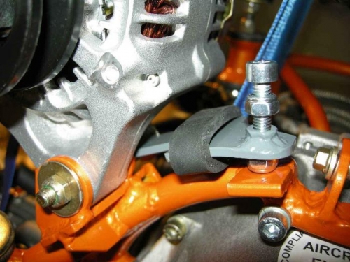
Alternator installation (11.01.2008)
(Later replaced with EPA power alternator, rear installation)
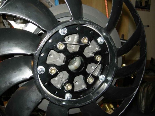
Cooling fan installation (19.01.2008)
 Cooling fan installed
 View front-aft
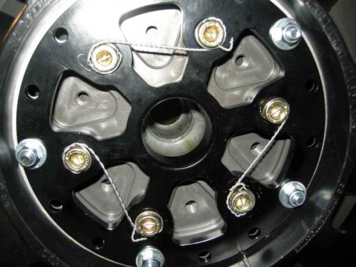
Pully installation, including fan wheel(19.01.2008)
![FP27012008A0003S[1]](https://kistleronline.ch/wp-content/uploads/2015/02/FP27012008A0003S1.jpg) Oliver, my son, pully Installation
Oliver, my son, pully Installation
![FP27012008A0003U[1]](https://kistleronline.ch/wp-content/uploads/2015/02/FP27012008A0003U1.jpg) Cut „Halsmutter“ M8 to about 17mm
Cut „Halsmutter“ M8 to about 17mm
![FP27012008A0003T[1]](https://kistleronline.ch/wp-content/uploads/2015/02/FP27012008A0003T1.jpg) …..and install
…..and install
Crew, ready to install engine (20.01.2008)
Marian and Oliver
![FP27012008A0003Z[1]](https://kistleronline.ch/wp-content/uploads/2015/02/FP27012008A0003Z1.jpg) Marian
Marian
![FP27012008A0003Y[1]](https://kistleronline.ch/wp-content/uploads/2015/02/FP27012008A0003Y1.jpg) Christina, the photographer!
Christina, the photographer!
Engine installation (20.01.2008)
![FP27012008A00041[1]](https://kistleronline.ch/wp-content/uploads/2015/02/FP27012008A000411.jpg) …ready….
…ready….
![FP27012008A00042[1]](https://kistleronline.ch/wp-content/uploads/2015/02/FP27012008A000421.jpg)
![FP27012008A00043[1]](https://kistleronline.ch/wp-content/uploads/2015/02/FP27012008A000431.jpg) Ready to lift half up
Ready to lift half up
Engine installed! (20.01.2008)
![FP27012008A00044[1]](https://kistleronline.ch/wp-content/uploads/2015/02/FP27012008A000441.jpg) …installed, aft section…
…installed, aft section…
![FP27012008A00045[1]](https://kistleronline.ch/wp-content/uploads/2015/02/FP27012008A000451.jpg) …Marian, very concentrated…
…Marian, very concentrated…
![FP27012008A00046[1]](https://kistleronline.ch/wp-content/uploads/2015/02/FP27012008A000461.jpg) Oliver and „Papi“
Oliver and „Papi“
![FP27012008A00047[1]](https://kistleronline.ch/wp-content/uploads/2015/02/FP27012008A000471.jpg)
![FP27012008A00048[1]](https://kistleronline.ch/wp-content/uploads/2015/02/FP27012008A000481.jpg) –
–
![FP27012008A00049[1]](https://kistleronline.ch/wp-content/uploads/2015/02/FP27012008A000491.jpg)
Cooling system (02.02.2008)
![FP06042008A0000Z[1]](https://kistleronline.ch/wp-content/uploads/2015/02/FP06042008A0000Z1.jpg) Left cooler, incl. Thermostat cooler
Left cooler, incl. Thermostat cooler
![FP06042008A00010[1]](https://kistleronline.ch/wp-content/uploads/2015/02/FP06042008A000101.jpg) …see Rotax water Thermostat on the left…
…see Rotax water Thermostat on the left…
![FP06042008A00011[1]](https://kistleronline.ch/wp-content/uploads/2015/02/FP06042008A000111.jpg) Rotax Thermostat
Rotax Thermostat
Cooling system (02.02.2008)
![FP03022008A0002W[1]](https://kistleronline.ch/wp-content/uploads/2015/02/FP03022008A0002W1.jpg) Note additional distance to have enough room for steering rod
Note additional distance to have enough room for steering rod
![FP03022008A0002X[1]](https://kistleronline.ch/wp-content/uploads/2015/02/FP03022008A0002X1.jpg) Tube from waterpump to R water-cooler
Tube from waterpump to R water-cooler
![FP03022008A0002Y[1]](https://kistleronline.ch/wp-content/uploads/2015/02/FP03022008A0002Y1.jpg) Connection between R cooler to L watercooler
Connection between R cooler to L watercooler
Clutch installation (02.02.2008)
Clutch: after tightening with 150Nm to max. 160Nm it must fit like picture 1 shows, if not, unscrew again and turn 1 or 2 teeth and try again. (this is to have tailrotor still connected in case something brakes in the coupling.)
![FP03022008A00035[1]](https://kistleronline.ch/wp-content/uploads/2015/02/FP03022008A000351.jpg) It has to look like this after tightening with 150Nm
It has to look like this after tightening with 150Nm
![FP03022008A00036[1]](https://kistleronline.ch/wp-content/uploads/2015/02/FP03022008A000361.jpg) Alu stripe to hold against during tightening
Alu stripe to hold against during tightening
![FP03022008A00037[1]](https://kistleronline.ch/wp-content/uploads/2015/02/FP03022008A000371.jpg) Clutch, ready to connect tailrotor shaft
Clutch, ready to connect tailrotor shaft
Engine Mount (02.02.2008)
![FP03022008A00032[1]](https://kistleronline.ch/wp-content/uploads/2015/02/FP03022008A000321.jpg) Left, front
Left, front
![FP03022008A00033[1]](https://kistleronline.ch/wp-content/uploads/2015/02/FP03022008A000331.jpg) left, aft
left, aft
![FP03022008A00034[1]](https://kistleronline.ch/wp-content/uploads/2015/02/FP03022008A000341.jpg) Engine stabilizer, below
Engine stabilizer, below
Oil system(16.02.2008)
Installation of oil-circuit system according Rotax 914 installation manual. To avoid damage due to vibration the oil pressure sensor is not directly mounted to the engine housing. Note that this installation needs an additional grounding of the sender (red wire)
![FP27052009A00002[1]](https://kistleronline.ch/wp-content/uploads/2015/02/FP27052009A000021.jpg) Oil Reservoir
Oil Reservoir
![FP27052009A00003[1]](https://kistleronline.ch/wp-content/uploads/2015/02/FP27052009A000031.jpg) Oil pressure Sender
Oil pressure Sender
![FP27052009A00004[1]](https://kistleronline.ch/wp-content/uploads/2015/02/FP27052009A000041.jpg) Remote installation of oil pressure Sender
Remote installation of oil pressure Sender
Gearbox-oil-cooling 1 (23.02.2008)
Main gear-box oil cooling system
![FP24032008A0002G[1]](https://kistleronline.ch/wp-content/uploads/2015/02/FP24032008A0002G1.jpg) Oil-pump for main gear, view from left
Oil-pump for main gear, view from left
![FP24032008A0002H[1]](https://kistleronline.ch/wp-content/uploads/2015/02/FP24032008A0002H1.jpg) …view from behind
…view from behind
![FP24032008A0002I[1]](https://kistleronline.ch/wp-content/uploads/2015/02/FP24032008A0002I1.jpg) …..view from right
…..view from right
Gearbox-oil-cooling 2 (24.02.2008)
Oil-cooler installation, in front of water-oil cooler. Oil runs from gearbox lower forward fitting to the filter, from filter to pump-IN, from pump-OUT into cooler and then from cooler back to the gearbox, upper rear fitting.
![FP24032008A00025[1]](https://kistleronline.ch/wp-content/uploads/2015/02/FP24032008A000251.jpg) Oil filter (above), below oil cooler
Oil filter (above), below oil cooler
![FP24032008A00026[1]](https://kistleronline.ch/wp-content/uploads/2015/02/FP24032008A000261.jpg) Main gearbox oil filter Installation
Main gearbox oil filter Installation
![FP24032008A00027[1]](https://kistleronline.ch/wp-content/uploads/2015/02/FP24032008A000271.jpg) Oil cooler
Oil cooler
Fuel System Installation 1 (22.03.2008)
To have exact fuel available at any moment during flight, I decided to install a Return Flow Controller from Matronics.
![FP24032008A0002J[1]](https://kistleronline.ch/wp-content/uploads/2015/02/FP24032008A0002J1.jpg) The best Fuelselector available in market….! (Andair, England)
The best Fuelselector available in market….! (Andair, England)
![FP24032008A0002K[1]](https://kistleronline.ch/wp-content/uploads/2015/02/FP24032008A0002K1.jpg) …how it looks from behind
…how it looks from behind
![FP24032008A0002L[1]](https://kistleronline.ch/wp-content/uploads/2015/02/FP24032008A0002L1.jpg) Forward Flow Transducer
Forward Flow Transducer
Fuel System Installation 2 (23.03.2008)
![FP06042008A00015[1]](https://kistleronline.ch/wp-content/uploads/2015/02/FP06042008A000151.jpg) Filter, pumps
Filter, pumps
![FP06042008A00016[1]](https://kistleronline.ch/wp-content/uploads/2015/02/FP06042008A000161.jpg) Pumps, fueltransducer, fwd and return flow
Pumps, fueltransducer, fwd and return flow
..then the line goes to the……
Fuel System Installation 3 (24.03.2008)
![FP06042008A00018[1]](https://kistleronline.ch/wp-content/uploads/2015/02/FP06042008A000181.jpg) ….to the carburator..
….to the carburator..
Also the fuel-return line has his Return Flow Transducer
Pumps, incl. fuel pressure sender for Dynon
Pick-up of „Rolling-Hangar“ (28.03.2008)
Today is another great day: Finally I could pick-up the „Rolling-Hangar“ together with my friend Noldi Schwaninger. The Klaesi team did a very nice job, see http://www.klaesi.ch/. The hangar is isolated and should keep the helicopter in a nice and friendly climate. Total length of the box is 7m50. Max. Driving speed is between 80-90kmh. Maximum allowed vehicle weight is 3.5 tons. There is still a payload of 1250kg available with the box mounted on the vehicle. (Remember: Helicopter should end-up with around 285kg)
Fuel System Installation 4 (31.03.2008)
Fuel-tank holder installation: The fixing with textile fixation straps is only for the temporary fixing of RH-tank good enough, for fix installation of L-tank a fixation with metal straps is required
![FP06042008A0001E[1]](https://kistleronline.ch/wp-content/uploads/2015/02/FP06042008A0001E1.jpg) Left tank protection
Left tank protection
![FP06042008A0001F[1]](https://kistleronline.ch/wp-content/uploads/2015/02/FP06042008A0001F1.jpg) L-Tank holder, TCU behind
L-Tank holder, TCU behind
![FP06042008A0001G[1]](https://kistleronline.ch/wp-content/uploads/2015/02/FP06042008A0001G1.jpg) R-Tank holder, protection
R-Tank holder, protection
TCU (02.04.2008)
Servo motor for waste gate, mounted behind LH tank holder
![FP06042008A0001I[1]](https://kistleronline.ch/wp-content/uploads/2015/02/FP06042008A0001I1.jpg) Gas cable, connected to governor/collective
Gas cable, connected to governor/collective
![FP06042008A0001J[1]](https://kistleronline.ch/wp-content/uploads/2015/02/FP06042008A0001J1.jpg) L-Carburetor
L-Carburetor
![FP06042008A0001K[1]](https://kistleronline.ch/wp-content/uploads/2015/02/FP06042008A0001K1.jpg) R-Carburetor
R-Carburetor
Trim System (26.04.2008)
Longitudinal / side trim
The movable rod of servomotor has to line with nose up and down bar of cyclic. Before fixing make sure the movable servomotor rod is fully extended. Warning: do not power the trim motor only to extend the rod, rather turn it out manually until you hear the „click“ from stop-switch!
Side trim: good to drill hole for the bolt when still room available, before installation of battery, etc.
![FP27042008A0002P[1]](https://kistleronline.ch/wp-content/uploads/2015/02/FP27042008A0002P1.jpg) Longitudinal Trim
Longitudinal Trim
![FP27042008A0002Q[1]](https://kistleronline.ch/wp-content/uploads/2015/02/FP27042008A0002Q1.jpg) Side Trim
Side Trim
Preparation of winch Installation (03.05.2008)
Preparation of winch, remote controlled, to pull helicopter up/down.
Sutter GmbH, Elektro-Seilwinde 2000lbs-900/1800kg f. Quads Linhai ua
4 ST x 504358 KFZ-RELAIS FRC6BA-1-DC12V 1XEIN 150 A, 1 ST x 190904 2-KANAL-RF-FERNBEDIENUNGSSET – FG
![FP03052008A0000E[1]](https://kistleronline.ch/wp-content/uploads/2015/02/FP03052008A0000E1.jpg) Remote control, 2 ch
Remote control, 2 ch
![FP03052008A0000F[1]](https://kistleronline.ch/wp-content/uploads/2015/02/FP03052008A0000F1.jpg) Whole set, ready to install
Whole set, ready to install
Rolling hangar, video system installation(04.05.2008)
Video installation:
2 ST x 855140 FUNK-ZUSATZKAMERA FÜR 853432
1 ST x 853432 FARB-TFT-RÜCKFAHRVIDEOSYSTEM FUNK
Service Bulletin 38 (10.05.2008)
SB 38, dated 5th May 2007 says:
The main tank (left) in the Charlie version is at a such distance from the exhaust manifold of cylunder 2 that it does not affect the tank by normal working. By supposition of a break of the exhaust manifold near the outlet of the cylinder 2, the exhaust gas at hot temperature could turn towards the tank, with negative consequences, therefore we suggest to apply a suitable protection on the surface of the tank near the manifold.
I decided to protect both tanks, R and L.
![FP12052008A0000X[1]](https://kistleronline.ch/wp-content/uploads/2015/02/FP12052008A0000X1.jpg) Left Tank, steel, covered with hi-speed tape
Left Tank, steel, covered with hi-speed tape
![FP12052008A0000Y[1]](https://kistleronline.ch/wp-content/uploads/2015/02/FP12052008A0000Y1.jpg) Additional Right Tank
Additional Right Tank
Installation of Battery, master Relay and Shunt (20.07.2008)
Due to EFIS installation (lighter instruments) and due to advice of other builders I decided to install the battery forwrd, below the cabin floor.
![FP20072008A0000S[1]](https://kistleronline.ch/wp-content/uploads/2015/02/FP20072008A0000S1.jpg) Battery and Shunt
Battery and Shunt
![FP20072008A0000T[1]](https://kistleronline.ch/wp-content/uploads/2015/02/FP20072008A0000T1.jpg) Battery Installation
Battery Installation
![FP20072008A0000U[1]](https://kistleronline.ch/wp-content/uploads/2015/02/FP20072008A0000U1.jpg) Master Fuse (80A), Master Relay and Shunt
Master Fuse (80A), Master Relay and Shunt
EGT probe Installation(11.10.2008)
![FP12102008A00008[1]](https://kistleronline.ch/wp-content/uploads/2015/02/FP12102008A000081.jpg) EGT, M8 screw, locking: M3
EGT, M8 screw, locking: M3
TCU Connection (11.10.2008)
The Mapper-Card is between the engine and the TCU-Box[/fusion_text]
![FP12102008A00005[1]](https://kistleronline.ch/wp-content/uploads/2015/02/FP12102008A000051.jpg) Mapper Card
Mapper Card
![FP12102008A00006[1]](https://kistleronline.ch/wp-content/uploads/2015/02/FP12102008A000061.jpg) Mapper card, mounted on top of engine wiring box
Mapper card, mounted on top of engine wiring box
![FP12102008A00007[1]](https://kistleronline.ch/wp-content/uploads/2015/02/FP12102008A000071.jpg) View from left side
View from left side
Battery Charging (18.10.2008)
I have installed a battery charger plug to keep the 12V Batt always at a good level. The „keep alive power“ for the internal back-up battery of the Dynon EFIS DEK 180 is only charged, if the plug is connected. This to prevent taking current from aircraft battery while stored (to avoid low battery voltage).
![FP19102008A0001Q[1]](https://kistleronline.ch/wp-content/uploads/2015/02/FP19102008A0001Q1.jpg) Battery Keep alive plug
Battery Keep alive plug
![FP19102008A0001R[1]](https://kistleronline.ch/wp-content/uploads/2015/02/FP19102008A0001R1.jpg) Plug with internal bridge from +12V to „keep alive pwr Dynon
Plug with internal bridge from +12V to „keep alive pwr Dynon
![FP19102008A0001S[1]](https://kistleronline.ch/wp-content/uploads/2015/02/FP19102008A0001S1.jpg) Eng Oil Chip Detector
Eng Oil Chip Detector
Instruments (01.11.2008)
Instruments, ready to connect everything!
![FP19072009A0002Q[1]](https://kistleronline.ch/wp-content/uploads/2015/02/FP19072009A0002Q1.jpg) DEK 180 on internal power
DEK 180 on internal power
![FP19072009A0002R[1]](https://kistleronline.ch/wp-content/uploads/2015/02/FP19072009A0002R1.jpg) …still something to do!
…still something to do!
![FP19072009A0002S[1]](https://kistleronline.ch/wp-content/uploads/2015/02/FP19072009A0002S1.jpg) …and the view half closed
…and the view half closed
EFIS, first tests (01.03.2009)
![FP06012012A00005[1]](https://kistleronline.ch/wp-content/uploads/2015/02/FP06012012A000051.jpg) Elec power on all instruments
Elec power on all instruments
Instruments with switching Panel
![FP01032009A0000M[1]](https://kistleronline.ch/wp-content/uploads/2015/02/FP01032009A0000M1.jpg) Not yet bundled
Not yet bundled
![FP27052009A00009[1]](https://kistleronline.ch/wp-content/uploads/2015/02/FP27052009A000091.jpg)
Connecting Tailboom to the Fuselage (25.04.2009)
![FP27052009A00008[1]](https://kistleronline.ch/wp-content/uploads/2015/02/FP27052009A000081.jpg)
Mounting of Tailboom, -Gearbox (25.04.2009)
![FP27052009A00005[2]](https://kistleronline.ch/wp-content/uploads/2015/02/FP27052009A000052.jpg) Tail gearbox
Tail gearbox
![FP27052009A00006[1]](https://kistleronline.ch/wp-content/uploads/2015/02/FP27052009A000061.jpg) Tal gearbox
Tal gearbox
![FP27052009A00007[1]](https://kistleronline.ch/wp-content/uploads/2015/02/FP27052009A000071.jpg) Tail rotor
Tail rotor
Anticollition light (26.05.2009)
LED beacon Its size (2.5″ dia. x 3″ high) Utilizing LED (Light Emitting Diode) technology, Whelen is able to provide the following advantages compared to existing light assemblies.
Features
* Lamp Life – light source has shown conservative lab life results greater than 20,000 hours
* Reduced Power Consumption – More efficient than alternative light sources
* No external power supply
* Reduced operating Costs
* Shock & Vibration Resistant – No fragile filament
* Utilizes State-of-the-Art Surface Mount Technology
* No EMI or RFI Interference
* FAA TSO-C96a Class III Approved
* Hard Coated Clear Polycarbonate Lens
* Unit complies with color requirements per FAR Parts 23, 25, 27 and 29 for Aviation Red
* Reduced Weight (0.55 lbs.)
* 3 year warranty
Specifications
* Lamp: LED (Light Emitting Diode)
* Voltage: 14 VDC or 28 VDC
* Input Current: 1.2 AVG @ 14 V
* LED Color: Aviation Red
* Approx. Life: 10,000 Hours
* Weight: 0.55 Lbs.
![FP27052009A0000E[1]](https://kistleronline.ch/wp-content/uploads/2015/02/FP27052009A0000E1.jpg)
![FP27052009A0000F[1]](https://kistleronline.ch/wp-content/uploads/2015/02/FP27052009A0000F1.jpg) Muffler, turbine (26.05.2009)
Muffler, turbine (26.05.2009)
View from below/behind to turbine, muffler.
See also water Thermostat.
![FP29082009A00005[1]](https://kistleronline.ch/wp-content/uploads/2015/02/FP29082009A000051.jpg) Muffler
Muffler
![FP27052009A0000I[1]](https://kistleronline.ch/wp-content/uploads/2015/02/FP27052009A0000I1.jpg) Intake Air to Turbine
Intake Air to Turbine![FP27052009A0000J[1]](https://kistleronline.ch/wp-content/uploads/2015/02/FP27052009A0000J1.jpg)
Air Filter mounting
Mounting of LH Fueltank (30.05.2009)
Left tank installation, including protection of heat to the tank from possible leaking exhaust pipe.
![FP26092009A0001R[2]](https://kistleronline.ch/wp-content/uploads/2015/02/FP26092009A0001R2.jpg) L-Tank, markings until 16 ltrs
L-Tank, markings until 16 ltrs
![FP31052009A00049[1]](https://kistleronline.ch/wp-content/uploads/2015/02/FP31052009A000491.jpg) Fixing at the top
Fixing at the top
![FP31052009A0004A[2]](https://kistleronline.ch/wp-content/uploads/2015/02/FP31052009A0004A2.jpg) …and view from below…
…and view from below…
Hobs meter Installation (31.05.2009)
To have the Hobsmeter recording only flight time you need a microswitch contact closing when collective is lifted. Watch the very thin steel arm below collective
![FP31052009A0004B[1]](https://kistleronline.ch/wp-content/uploads/2015/02/FP31052009A0004B1.jpg) Hobs meter, as installed in instrument Panel
Hobs meter, as installed in instrument Panel
![FP31052009A0004C[1]](https://kistleronline.ch/wp-content/uploads/2015/02/FP31052009A0004C1.jpg) Micro switch with thin steel arm
Micro switch with thin steel arm
Undercarriage (18.07.2009)
![FP19072009A0002T[1]](https://kistleronline.ch/wp-content/uploads/2015/02/FP19072009A0002T1.jpg) Transport wheels
Transport wheels
![FP19072009A0002U[1]](https://kistleronline.ch/wp-content/uploads/2015/02/FP19072009A0002U1.jpg) Step
Step
![FP19072009A0002V[2]](https://kistleronline.ch/wp-content/uploads/2015/02/FP19072009A0002V2.jpg) Rotor blades (25.07.2009)
Rotor blades (25.07.2009)
The leading edge of both rotor blades are covered with 3M Polyurethane Protective Tape 8561. The tape sells normaly only as 33m x 10cm rolls. I got 4m thanks to a friend. I used 1.60 m on each blade to protect the leading edge.
This is to allow flights in light rain and as a general protection.
![FP15012012A00002[1]](https://kistleronline.ch/wp-content/uploads/2015/02/FP15012012A000021.jpg) 3M Polyurethane Protective Tape 8561
3M Polyurethane Protective Tape 8561
Very first engine run (01.08.2009)
The great moment came on 1st August 2009: A great day, after about 3 years of building the very first engine run!
Engine temperatures, pressures, engine rpm all within limits and correct indication.
Missing was the rotor rpm indication. This later turned out that there was a mistake in the wiring leading to a defect on the voice warning card. This problem could be fixed after sending the unit to the manufacturer.
This is a great opportunity to say „thank you very much“ to my construction adviser Meinrad Frey, to my neighbor Armin Egli and of course also to my wife Christina!
As the workshop is quite at high altitude (1480m above sea level) I had to dislocate the helicopter during the winter down into a hall of a good friend. See the following link to see a nice video.
![FP20122009A00008[2]](https://kistleronline.ch/wp-content/uploads/2015/02/FP20122009A000082.jpg) Very first run, a bit smoke!
Very first run, a bit smoke!
![FP20122009A00009[2]](https://kistleronline.ch/wp-content/uploads/2015/02/FP20122009A000092.jpg) After 24Min, still all o.k.
After 24Min, still all o.k.
![FP20122009A0000A[2]](https://kistleronline.ch/wp-content/uploads/2015/02/FP20122009A0000A2.jpg) Happy, all went fine!
Happy, all went fine!
Heat Protection, Water Reservoir (08.08.2009)
Turbine can get very hot, protection of water tubes makes sence.
Heatprotection
![FP29082009A00006[1]](https://kistleronline.ch/wp-content/uploads/2015/02/FP29082009A000061.jpg) Fixing left side
Fixing left side
![FP29082009A00007[1]](https://kistleronline.ch/wp-content/uploads/2015/02/FP29082009A000071.jpg) Cooling water: relief on highest Point
Cooling water: relief on highest Point
Fuel Quantity Calibration (19.09.2009)
Fuel Tank left: Useable fuel quantity 30.6 liters, not useable 1 liter. The fuel probe is a Princeton Capacitive Fuel Level Probe, 5 set point model.
First: calibrate the fuelprobe, EMPTY, 1/4 set point, 1/2 set point, 3/4 set point and FULL and then the calibration in EFIS/EMS according DEK180 Manual.
Left Tank, total 31.6 Liters
![FP26092009A0001S[2]](https://kistleronline.ch/wp-content/uploads/2015/02/FP26092009A0001S2.jpg) Placard left tank
Placard left tank
![FP26092009A0001T[2]](https://kistleronline.ch/wp-content/uploads/2015/02/FP26092009A0001T2.jpg) Princeton, 5SP model
Princeton, 5SP model
Fuel Quantity Calibration (20.09.2009)
Fuel quantity is very accurate; tolerance is 0.5 liter over the whole tank quantity. While actual quantity in tank is almost 11 liters, indication on EFIS is 10.5 liters. The yellow range starts at 10 liters, this corresponds to about 30 minutes flight time. The red range starts at 4 liters; this is shortly after the mechanical low fuel level warning light, set at 5 liters, mounted in left tank, will come on.
At 4 liters remaining fuel the EFIS warning is also readable on headset, the 8 minutes should be sufficient to make an immediate landing.
![FP26092009A0001U[1]](https://kistleronline.ch/wp-content/uploads/2015/02/FP26092009A0001U1.jpg) Almost 11 Liters in tank
Almost 11 Liters in tank
![FP26092009A0001V[1]](https://kistleronline.ch/wp-content/uploads/2015/02/FP26092009A0001V1.jpg) EMS: Fuel page
EMS: Fuel page
![FP26092009A0001W[1]](https://kistleronline.ch/wp-content/uploads/2015/02/FP26092009A0001W1.jpg) EFIS & Fuel page
EFIS & Fuel page
1st Testrun with rotor blades installed (21.11.2009)
After installation and static balancing of both rotor blades we were eager to find out about how it feels like when the rotor was turning.
1st test run was with weight on skids (about 70kgs each side), this to avoid any problems in case of heavy vibrations.
Result: almost no vibrations!
The decision was to remove the weight for the second run
The run was very smooth as well, in fact compared to a Robinson: I was never starting up an R22 with such low vibrations!
Engine removal after overspeed (12.02.2010)
I publish these pictures because in aviation we have the tradition, that we should talk about our mistakes so that others must not make them again!
After first rotor test runs, the engine had logged 1 hour and 52 minutes only, I was checking the setting in the TCU(turbine control unit) again and discovered an engine over speed in the stored data file. According Rotax maintenance manual rpm more than 6200 rpm means an engine overhaul!
Reason for the overspeed: My mistake, I selected initially for the very first engine run the wrong engine-rpm-probe for the EFIS input!
As a consequence I had to remove the engine and drive it to Munich for a complete overhaul and pick it up 4 weeks later again! (One weekend to remove it and 4 days Easter-holiday to install it again!)
Lessons learned: Never run the freshly installed engine for the first time without controlling and observing engine rpm via data link and laptop!
Quite an expensive mistake, but after engine overhaul the TBO was increased from 1500 hours to 2000 hours, at least that!
The engineers at Franz in Munich did a very nice job, I could pickup the engine again after about 4 weeks only. By the way: During the very first engine run I found an rpm difference between EFIS indication and TCU rpm of only about 10 rpm!
![FP01052010A00002[2]](https://kistleronline.ch/wp-content/uploads/2015/02/FP01052010A000022.jpg) What a picture: engine removed again!
What a picture: engine removed again!
![FP01052010A00003[2]](https://kistleronline.ch/wp-content/uploads/2015/02/FP01052010A000032.jpg) Transport to Rotax dealer Franz in Munich
Transport to Rotax dealer Franz in Munich
![FP01052010A00004[2]](https://kistleronline.ch/wp-content/uploads/2015/02/FP01052010A000042.jpg)
One month later: Servicable engine
Markings, HB-YNB (26.04.2010)
This nice job was done by a company called
SIGN-FACTORY Schilderhersteller GmbH
Graf-Maximilian-Straße 18
6845 Hohenems, Austria,
the owner’s name is Patrick Brunner, e-mail: patrick.brunner@indepro.ch
![FP01052010A00005[2]](https://kistleronline.ch/wp-content/uploads/2015/02/FP01052010A000052.jpg) Selina, working very concentrated!
Selina, working very concentrated!
![FP01052010A00006[2]](https://kistleronline.ch/wp-content/uploads/2015/02/FP01052010A000062.jpg) Now it’s already Helicopter NB!
Now it’s already Helicopter NB!
![FP03102010A0001X[2]](https://kistleronline.ch/wp-content/uploads/2015/02/FP03102010A0001X2.jpg) Left side already finished
Left side already finished
W & B, weighing of helicopter (22.05.2010)
Weighing of project is always an exciting moment!
To keep it short: 301 kgs, with pilot 381 kgs!!
![FP07082010A00019[1]](https://kistleronline.ch/wp-content/uploads/2015/02/FP07082010A000191.jpg) Center of Gravity by common sence!
Center of Gravity by common sence!
![FP07082010A0001A[1]](https://kistleronline.ch/wp-content/uploads/2015/02/FP07082010A0001A1.jpg) Weighing Team: Kari Haller and Meinrad Frey
Weighing Team: Kari Haller and Meinrad Frey
![FP07082010A0001B[1]](https://kistleronline.ch/wp-content/uploads/2015/02/FP07082010A0001B1.jpg) Weighing
Weighing
![FP15012012A00003[1]](https://kistleronline.ch/wp-content/uploads/2015/02/FP15012012A000031.jpg) Fotoshooting! (03.10.2010)
Fotoshooting! (03.10.2010)
![FP15012012A00004[1]](https://kistleronline.ch/wp-content/uploads/2015/02/FP15012012A000041.jpg)
![FP15012012A00005[1]](https://kistleronline.ch/wp-content/uploads/2015/02/FP15012012A000051.jpg) Instruments, hall (03.10.2010)
Instruments, hall (03.10.2010)
Helicopter is ready to be inspected by FOCA.
I could finish my helicopter in the hall of Baumgartner Ernst, Markus and Peter. Thank you very much!
![FP03102010A0001T[1]](https://kistleronline.ch/wp-content/uploads/2015/02/FP03102010A0001T1.jpg) Instruments
Instruments
![FP03102010A0001S[1]](https://kistleronline.ch/wp-content/uploads/2015/02/FP03102010A0001S1.jpg) Instruments
Instruments
![FP03102010A0001V[2]](https://kistleronline.ch/wp-content/uploads/2015/02/FP03102010A0001V2.jpg) Lobag Maschinenbau
Lobag Maschinenbau
![FP03102010A0001U[1]](https://kistleronline.ch/wp-content/uploads/2015/02/FP03102010A0001U1.jpg) Outside, ready to fly! (03.10.2010)
Outside, ready to fly! (03.10.2010)
Fotoshooting on a very nice Sunday.
![FP03102010A0001W[2]](https://kistleronline.ch/wp-content/uploads/2015/02/FP03102010A0001W2.jpg) FOCA Inspection (29.10.2010)
FOCA Inspection (29.10.2010)
FOCA Inspection, last hurdle before receivieng the permit to fly!
![FP03112010A00002[1]](https://kistleronline.ch/wp-content/uploads/2015/02/FP03112010A000021.jpg) Hanspeter Bellwald & Leo Halberstadt, FOCA
Hanspeter Bellwald & Leo Halberstadt, FOCA
![FP03112010A00003[1]](https://kistleronline.ch/wp-content/uploads/2015/02/FP03112010A000031.jpg) All done!
All done!
![FP03112010A00004[1]](https://kistleronline.ch/wp-content/uploads/2015/02/FP03112010A000041.jpg) PERMIT TO FLY!
PERMIT TO FLY!
Very first flight! (20.11.2010)
Today was the day, I was dreaming since summer 2006!
I made my very first flight with my helicopter!
Charlie Bachmann, the testflight Advisor was of great help. Thanks to his experience we could do 3 flights with a total of 1h35 flying time!
![FP06012012A00004[1]](https://kistleronline.ch/wp-content/uploads/2015/02/FP06012012A000041.jpg) What a Feeling!
What a Feeling!
![FP06012012A00003[1]](https://kistleronline.ch/wp-content/uploads/2015/02/FP06012012A000031.jpg)
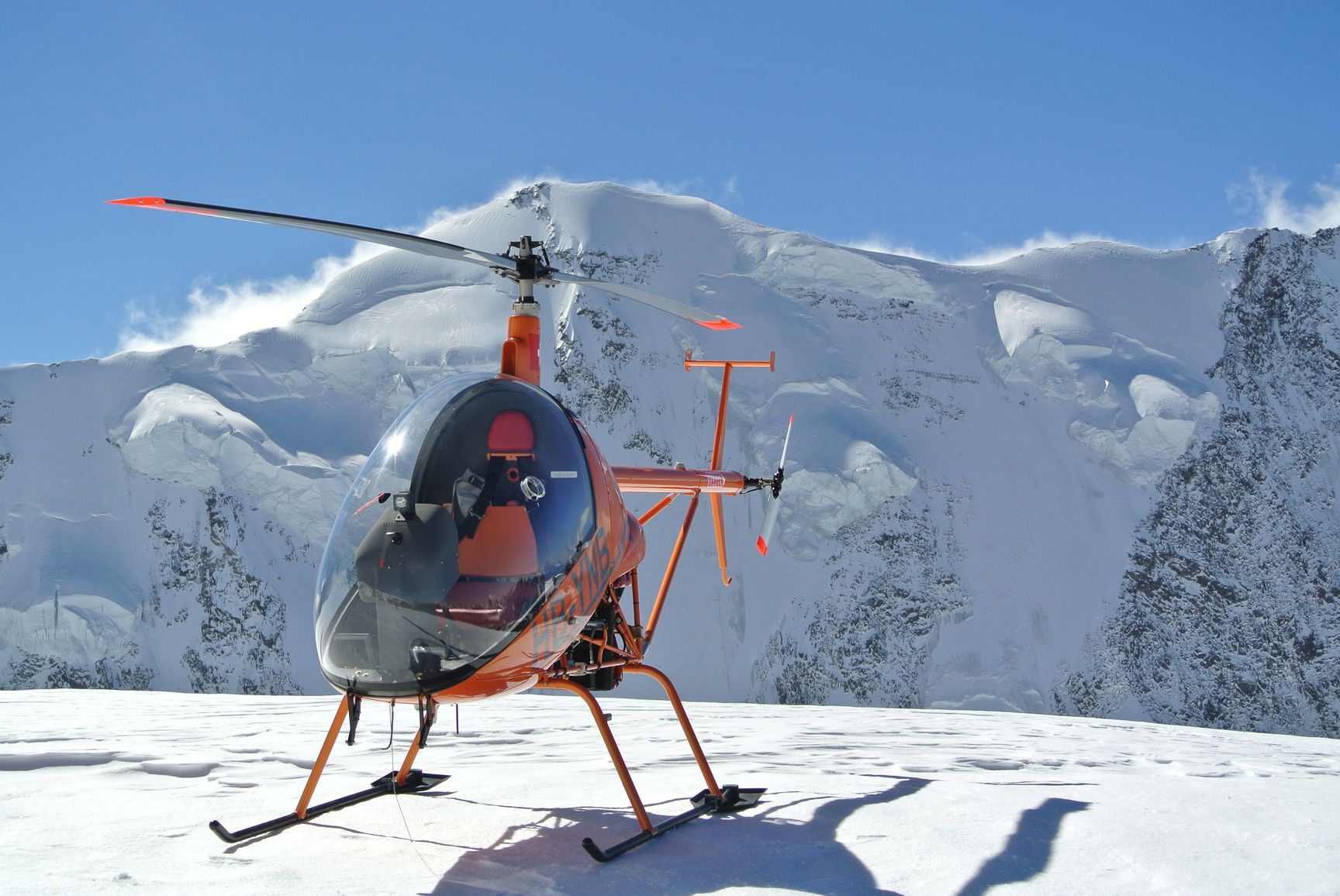
![FP06012012A00002[1]](https://kistleronline.ch/wp-content/uploads/2015/02/FP06012012A000021.jpg) First landing at high altitude (22.09.2011)
First landing at high altitude (22.09.2011)
After my mountain examination flight and Robinson R44 type rating I had to do a mountain flight with my Kompress! At that time the ski’s were not yet installed, as you easily can see!
Landing place is called Huefifirn, next to the Planurahuette.
For landing at another place in the eastern part of Switzerland see: Madrisahorn
Look at the density altitude!
![FP06012012A00006[1]](https://kistleronline.ch/wp-content/uploads/2015/02/FP06012012A000061.jpg) Landing in almost fresh snow
Landing in almost fresh snow
![FP06012012A00007[1]](https://kistleronline.ch/wp-content/uploads/2015/02/FP06012012A000071.jpg) Later installed
Later installed
Intercooler Installation (22.10.2011)
The maximum airbox temperature should never be higher than 88 ° celsius, above this temperature the waste-gate of the turbine will open to bypass air.
Since this would be dangerous during approach or take-off, I decided to install an intercooler to stay away from the 88 degrees.
Everything worked fine from the beginning and was tested during a flight to Huefifirn, Vorab and Grap Sogn Gion
___________________________________________________
This installation has been removed and I installed normal Rotax Airbox again. It contributed to an incident I had in October 2012.
At this moment I installed a temperature Sender in the airbox, I never noted more then 75 °, so an aircooler is not required and I have been up to 4150m in the meantime!
![FP06012012A00008[1]](https://kistleronline.ch/wp-content/uploads/2015/02/FP06012012A000081.jpg) View from left
View from left
![FP06012012A00009[2]](https://kistleronline.ch/wp-content/uploads/2015/02/FP06012012A000092.jpg) View from right
View from right
![FP06012012A0000A[2]](https://kistleronline.ch/wp-content/uploads/2015/02/FP06012012A0000A2.jpg) Corvatsch, 3200 m above sea Level
Corvatsch, 3200 m above sea Level
Lightweight Lithium Ion starter battery (22.12.2011)
Battery Fact Sheet Super B 5200, http://www.super-b.com/
Product Description
Lightweight Lithium Ion starter battery, 1.98 lb / 900 gram,
This newly developed battery is designed to replace the much heavier 10 to 12 Ah lead/acid battery. The super B 5200 is based on the safe Lithium Iron Phosphate technology (LiFePO4), better known as Lithium Ion.
The super B 5200 delivers up to 300 Cranking Amps.
The super B 5200 offers many advantages over conventional 10 to 12 Ah lead/acid batteries:
Weighs less: as much as 80% weight saving; 1.98 lb / 900 grams;
Recharges many times faster: within 5 minutes after starting your engine the battery will be recharged;
Is much smaller: 1/3 or less of the space; 4.49 inch, 3.2 inch, 2.4 inch (WxHxD) / 114mm x 81.25mm x 62mm (WxHxD);
Has a longer service life: more than 5 years instead of 2 to 3 years;
Has a low self-discharge rate.
Safety: Super B batteries are based on Lithium Iron Phosphate technology (LiFePO4). This so called Lithium Ion technology as used in the super B batteries is the safest Lithium Ion technology today.
Capacity
super B 5200 refers to 5.2 Ah (Amps/Hour), which represents the real nominal capacity under maximum continuous load. How different this is from lead / acid batteries where manufactures provide a 20 hour rating. For example the 10 Ah lead / acid batterie can be discharged over a period of 20 hours with a 0.5 Amp load. This is not very practical, as the same 10 Ah battery discharged with a 2,5 Amp load, for example a 25 Watt light bulb, will yield no more than 2.2 Ah of energy. The lead-acid battery, therefore, has less capacity when the load increases, which means that you can start more often with the super B.
![FP15012012A00009[2]](https://kistleronline.ch/wp-content/uploads/2015/02/FP15012012A000092.jpg) See the Difference!
See the Difference!
![FP15012012A0000A[2]](https://kistleronline.ch/wp-content/uploads/2015/02/FP15012012A0000A2.jpg) Before
Before
![FP15012012A0000B[2]](https://kistleronline.ch/wp-content/uploads/2015/02/FP15012012A0000B2.jpg) After
After
Cabin Heater Installation (15.01.2012)
To have it nice and warm an Eberspächer B1 LC Air Heater is installed.
To compensate the additional weight a lightweight Lithium Iron starter battery, specially developed for motorcycles, jet-skis, snowmobiles, ATVs and Quads was installed.
![FP15012012A00006[1]](https://kistleronline.ch/wp-content/uploads/2015/02/FP15012012A000061.jpg) View from right below
View from right below
![FP15012012A00007[1]](https://kistleronline.ch/wp-content/uploads/2015/02/FP15012012A000071.jpg) Air Inlet Cabine, R, very important: take the air to heat from inside the cabin as well, if not, heater will overheat and shut down! ( due to (almost) blocked airstream if the cabin is closed)
Air Inlet Cabine, R, very important: take the air to heat from inside the cabin as well, if not, heater will overheat and shut down! ( due to (almost) blocked airstream if the cabin is closed)
![FP15012012A00008[1]](https://kistleronline.ch/wp-content/uploads/2015/02/FP15012012A000081.jpg) Control unit, ON/OFF and Temp selector
Control unit, ON/OFF and Temp selector
Status of the helicopter right now (February 2015)
Helicopter is upgraded to model Kompress Charlie 2 (EPA power alternator, water-oil heatexchanger, means new Thermostat and watercooler, carbon blades, carbon stabilizer) and I just made my highest landing you can do in Switzerland.
Video: Monte-Rosa Satteltole, 4’150m/13’615ft!
Hallo und vielen Dank für die ausführliche Beschreibung. Sehr spannend zu lesen und sehr informativ für jemanden, wie mich, der in diese Richtung des fliegens möchte.
Mit freundlichen Grüßen
Siegfried Habermann-Klar
Dear Mr Kistler,
first of all I would like to congratulate you for the very interesting description of the building of your CH7 Kompress. I have read it with a great interest. The quality of the pictures is very good and your comments are useful. I was also really impressed by the different places where you have landed.
Like you, I’m interesting in building a ultra light helicopter and I’m hesitating between different types : CH7, Cicare Spirit or CH8, CH77 Ranabot or the Dynali H3.
I have written below a list of different questions I’m thinking about. It would be very kind to you if you can take time to answer these questions. It will help me a lot.
How to choose the right helicopter:
I wonder if you can tell me more about your experience and your analysis of the subject in order to help me to take a decision? You may have compare different helicopters before to choose the CH7. What did you take into consideration? What was your conclusion and why?
I wanted to be able to fly to the highest mountain landing sites (4’150m) we have in Switzerland. The CH-7 is in the market since a long time and they have constantly improved the construction. I would still decide to build the CH-7 Kompress today.
What about maintenance: As the builder of the helicopter, I can do the maintenance myself
What are the maintenance costs?
Do you need to come back to factory for maintenance? Yes, with the tailrotor, for the yearly inspection, about 500 Euro. Once a year I fly or drive down to see a very good maintenance team in Torino: Davide Borgna with his team, http://www.sky-tech145.com. I think, it is a good idea to have someone else looking at your helicopter from time to time.
Confidence in the machine :
According to your experience, what is the reliability of the CH7? Is it a trustable helicopter?
Did you have failure issue? I had absolutely no problem up to now, all the problems I had, was my fault. Yes, I trust the helicopter very much!
Buying a used one :
What do you think about buying a used CH7 ? What are the most important things to care about? Ask Davide Borgna
What about flight :
What are you feelings about the CH7? How does it fly? What is its behavior in wind or at high altitude? See my video, it tells you all: https://youtu.be/QRgTP2LMff4?si=P9furF_ysnoqsFsT
The CH7 is a 2 seat in tandem, how is it with 2 people? At low altitude no problem, but you have to consider the payload! Your passenger must be slim! If I have guests, I take the R44. (The empty weight of my helicopter is 300kg, I am 80kg, the max T/O weight is 450kg, so, only 70kg for passenger and fuel!)
Thank you so much for the time you may spend to answer to these questions.
Best regards.
Philippe Muller
Dear Philippe
I inserted the answers right in the text above, i hope, it helps!
Best regards
Charly
Dear Karl,
thank you very much for your answers. Yes, it helps me.
I wish you to continue to have a lot of nice flights with your helo.
Best regards.
Philippe
I had the pleasure to talk to you today, 26.10.15, in Wägital. Very impressive, your achievement with your „Experimental“. Rgds Kurt